Supercharge Your Rip Fence
Smart base supports a host of essential accessories

Synopsis: When Bob Van Dyke needed an auxiliary rip fence that he could easily attach and remove without damaging the tablesaw’s main fence or sacrificing accuracy, he came up with this supercharged base, which is both practical and versatile. The base is made from 3⁄4-in. Baltic-birch plywood, fastened into an H-shape that straddles the saw’s rip fence. A pair of toggle clamps applies pressure to the back of the base, drawing the front tightly into place. After the base is built, it’s a simple matter to equip it with the add-on fences you need for tasks such as cutting rabbets, tenons, raised panels, and other workpieces.
Your tablesaw’s rip fence is an integral part of the tool. It performs the basic task of guiding the workpiece parallel to the blade. without it, you can’t rip wood safely or accurately.
But that’s just the beginning of its usefulness. It is also common practice to clamp any number of jigs and auxiliary fences to the rip fence for specific jobs like cutting a rabbet in the edge of a board or a bevel on a raised-panel door. The problem with this is the clamping, and the low height of the fence. Put the clamps low and they hinder the workpiece sliding by; too high, and the extra fence won’t stay plumb.
I decided it was time to make something better, so I borrowed an idea from a special fence I had made years ago. what I needed was an auxiliary fence that I could easily attach and remove without damaging the main fence or sacrificing accuracy. I wanted to do it without putting clamps in the way of the work, and I wanted to make it easy to attach a variety of useful jigs.
No one sets up shop just to make jigs, but I think you’ll find it’s worth the time to build the base and the add-ons I describe here. You will probably find even more uses as you put the system to work.
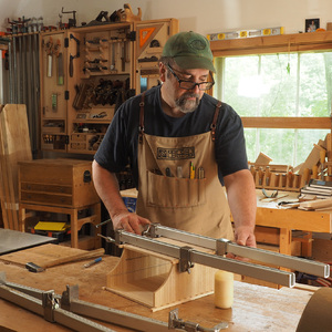
In terms of usefulness, this auxiliary fence base gets the prize. By adding special-purpose fences, common tasks such as cutting rabbets and tenons and panel-raising are all greatly simplified. The base is made from 3 ⁄4-in. Baltic-birch plywood, fastened into an H-shape that straddles the saw’s rip fence. A pair of toggle clamps applies pressure to the back of the base, drawing the front tightly into place. The base doesn’t need to fit the width of your rip fence precisely because the clamps pull it into position.
Start by creating the bridge from two lengths of the plywood. Face-glue and screw or nail the pieces together and then rip the bridge to width. Make sure the long edges are parallel: They will be glued into dadoes in the backs of the two uprights to form the H.
Cut the dadoes in the uprights using a 3⁄4-in. dado cutter at the tablesaw. Take multiple passes to sneak up on the fit.
For the full article, download the PDF below.


Comments
Very good article. I'm making this but I'm wondering what the two outside holes are for that are close to the large hanging holes. They don't appear to have the threaded inserts but should I put them in there for some other purpose?
From what I understand, I built this a few months ago...The outer holes are for hanging purposes when you're not using it.
I am building this as well. is it five threaded holes or seven? the drawings show seven but the video and other drawings only show five. But the tall melamine fence has seven.. anyone know? thanks
rjherald
I'll reach out to Bob, but I doubt he remembers, or still has this particular fence still. Also, it doesn't really matter as long as the fence is secured.
Were the previous comments ever addressed? I understand that it must be difficult to go back to an old issue and try to figure out what was going on. Nevertheless, it would be appreciated if Fine Woodworking would at least act as if they take seriously apparent inconsistencies with dimensions of drawings provided in their magazine. It is frustrating to be treated as if questions and comments such as these are mere annoyances to the editors and authors to be treated with disdain.
I'm also trying to build this fence and at lease three notations in the drawing on page 58 of the article are not consistent.
1. The upper part of the drawing says that there should be 9 holes, but only 7 are shown. That appears to be a typographical error: I don't see 9 holes in any other drawing or photograph.
2. In the bottom part of the drawing, as user-6151007 noted, there are two small holes which are not described or depicted elsewhere in the article.
3. Based on my calculations, the 1-in. dimension from the bottom of the front upright to the center of the large holes cannot be correct, as the diameter of the large holes appears to be 1-1/4 in (see p. 60). However, if the 1-in. dimension were to be referring to the location of the bottom of the hole, then all the other dimensions work out. A total height of 5-1/2 in. is obtained from 3-1/4 in. to the top of the large hole plus 1-1/4 in. diameter for the hole, and 1 in. from the bottom of the front upright.
For posterity and because I find the projection of misunderstanding as another's failing irksome:
3. How is it not possible to drill a 1-1/4" hole on a center 1" up from an edge? If the radius were greater than one inch, sure . . . but it's not.
2. The wee hole just outside the hang hole is shown with an insert in the very first photo.
1. There are 9 holes, if you count the aforementioned holes. Which again, are pictured with inserts in the very first photo.
As Mr Strano points out, the exact hole count doesn't matter. If what you are attaching to it is secure, get after it. More holes mean more options when attaching the auxiliary bits.
Log in or create an account to post a comment.
Sign up Log in